
When learning basic electronics, one of the first concepts you’ll encounter is series vs parallel circuit. Both circuit types are used to connect electrical components, but they behave very differently when electricity flows through them.
Knowing the difference helps you understand how household wiring works, why some Christmas lights go out together, and why your home’s outlets keep working even if one appliance is unplugged.
This guide explains series and parallel circuits in plain English, with examples, comparison tables, diagrams, advantages, disadvantages, and practical uses.
What Is a Circuit?
An electrical circuit is a closed pathway that enables electric current to flow from a power source, through one or more electrical components, and then return to the source. If you’re new to electrical systems, What Is a Circuit explains these basic principles in greater detail before comparing different circuit designs.
A simple circuit usually includes:
- A power source (battery or power supply)
- Conductive wires
- A switch (optional)
The way electrical components are connected determines whether a circuit is a series circuit or a parallel circuit. In a series circuit, all components are connected along a single path, so the same electric current flows through each one.
What Is a Series Circuit?
A series circuit connects all electrical components in a single continuous path.
For a more detailed explanation of this configuration, What Is a Series Circuit explores how current flows through a single path and where this design is commonly used.
current has only one route to travel. Because every component is connected in a single continuous loop, the same current passes through each device in sequence
If one component stops working or is disconnected, the entire circuit is interrupted.
How It Works
Imagine several light bulbs connected one after another.
Electricity flows like this:
Battery → Bulb 1 → Bulb 2 → Bulb 3 → Battery
Since there is only one path, every component carries the same current.
What Is a Parallel Circuit?
A parallel circuit connects electrical components across multiple branches, giving electric current more than one path to follow
Each branch receives electrical power independently.
If one component fails, the others continue operating normally.
How It Works
Each light bulb connects directly across the power source.
Current splits into different branches before returning to the battery.
This design makes parallel circuits much more reliable for everyday electrical systems.
Series Circuit vs Parallel Circuit
The easiest way to understand the differences is through a comparison table.
| Feature | Series Circuit | Parallel Circuit |
|---|---|---|
| Current Path | One path | Multiple paths |
| Voltage | Divided among components | Same across every branch |
| Current | Same everywhere | Divides between branches |
| If One Component Fails | Entire circuit stops | Other branches continue working |
| Brightness of Bulbs | Usually decreases with more bulbs | Bulbs stay equally bright |
| Wiring Complexity | Simple | More complex |
| Reliability | Lower | Higher |
| Common Applications | Flashlights, simple electronics | Homes, offices, vehicles |
This table summarizes the main differences in the series circuit vs parallel circuit comparison.
How Electricity Behaves
Understanding voltage and current makes the comparison much easier.
Learning Volts vs Amps also helps explain why voltage behaves differently in series and parallel circuits while current follows different rules depending on the circuit design.
In a Series Circuit
- Voltage is shared among components.
- Resistance increases as more components are added.
Example:
A 12-volt battery powering three identical bulbs gives each bulb about 4 volts.
In a Parallel Circuit
- voltage remains the same across every branch.
- current is shared among the available branches according to the resistance of each one.
- Components work independently.
Example:
Three bulbs connected to a 12-volt battery each receive the full 12 volts.
Once voltage and current are understood, it’s much easier to How to Calculate Watts when determining the electrical power used by different devices and circuits.
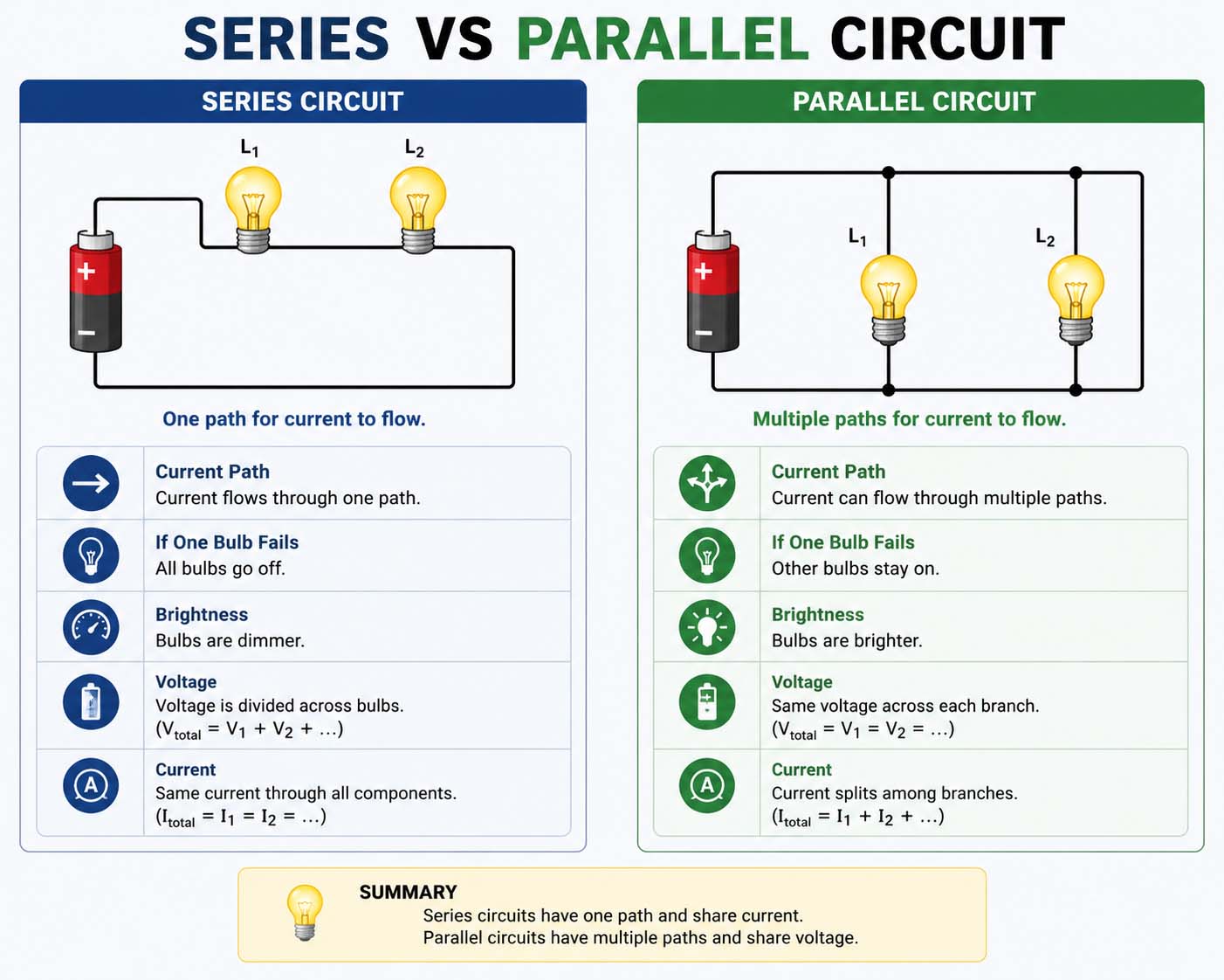
Series vs Parallel Circuit Diagram
A simple visual comparison makes the wiring differences easier to understand.
Series Circuit Diagram (Text Illustration)
Battery
 (+)
  |
[Bulb]
  |
[Bulb]
  |
[Bulb]
  |
 (-)
Battery
Only one electrical path exists.
Parallel Circuit Diagram (Text Illustration)
          |--[Bulb]--|
Battery --|--[Bulb]--|-- Battery
          |--[Bulb]--|
Each branch creates its own path back to the battery.
A series vs parallel circuit diagram quickly shows why one failed component affects only a series circuit.
Advantages of a Series Circuit
Series circuits still have many useful applications.
Benefits include:
- Easy to build
- Requires less wiring
- Lower installation cost
- Simple troubleshooting
- Good for learning electronics
- Works well in basic control systems
Because of their simplicity, students often build series circuits during science classes.
Advantages of a Parallel Circuit
Parallel circuits are the preferred design for most modern electrical systems because they provide reliable, efficient, and independent operation of connected devices
Benefits include:
- Components operate independently
- Greater reliability
- Full voltage reaches every device
- Easy to add more branches
- Better overall performance
- One failure does not stop everything
These advantages explain why homes and commercial buildings almost always use parallel wiring.
Disadvantages of Each Circuit Type
Every circuit design has trade-offs.
Series Circuit
Drawbacks include:
- One failed component stops everything
- Voltage drops across multiple devices
- Components affect one another
- Limited flexibility
Parallel Circuit
Possible disadvantages include:
- Requires more wiring
- Installation is more complex
- Higher material cost
- Larger total current demand
Despite these drawbacks, the added reliability usually makes parallel circuits the better option.
Real-World Examples
Understanding where each circuit is used makes the topic easier to remember.
Common Series Circuit Applications
- Flashlights
- Older Christmas light strings
- Basic educational kits
- Some battery-powered toys
- Simple switches
Common Parallel Circuit Applications
- Home electrical outlets
- Ceiling lights
- Office buildings
- Street lighting
- Vehicle electrical systems
- Computer power distribution
Nearly every modern building relies on parallel circuits.
Parallel Circuit vs Series Circuit: Which Is Better?
People often search parallel circuit vs series circuit when deciding which design is better.
There isn’t one answer for every situation.
Choose a series circuit when:
- Simplicity matters
- Few components are needed
- Low cost is a priority
- Educational demonstrations are the goal
Choose a parallel circuit when:
- Reliability matters
- Devices must operate independently
- Full voltage is required
- Future expansion is expected
For almost all residential and commercial installations, parallel circuits are the preferred choice.
Step-by-Step: How to Identify a Circuit
If you’re looking at an unfamiliar circuit, follow these steps.
Step 1: Find the Power Source
Locate the battery or power supply.
Step 2: Follow the Wires
See how electricity can travel.
- One continuous path = Series
- Multiple branches = Parallel
Step 3: Count the Paths
If current has only one possible route, it’s a series circuit.
If current can choose different routes, it’s a parallel circuit.
Step 4: Check the Components
Observe whether devices are connected one after another or side by side.
Common Mistakes Beginners Make
Many new electronics students confuse these ideas.
Common mistakes include:
- Assuming all circuits work the same
- Mixing series and parallel symbols
- Forgetting voltage distribution
- Ignoring current flow
- Connecting batteries incorrectly
- Overloading circuit branches
Practicing with simple diagrams helps avoid these errors.
Troubleshooting Circuit Problems
When a circuit isn’t working, these checks can save time.
| Problem | Possible Cause | Solution |
|---|---|---|
| Entire circuit stops | Broken wire in series circuit | Inspect every connection |
| One light won’t turn on | Burned-out bulb | Replace the bulb |
| Dim lights | Voltage drop | Reduce the number of series components |
| Fuse blows | Excess current | Check wiring and load |
| Component overheats | Short circuit | Disconnect power and inspect wiring |
Safety always comes first when troubleshooting electrical systems.
Best Practices for Building Circuits
Whether you’re working on a classroom project or a hobby electronics kit, following a few basic practices improves both safety and performance.
- Turn off power before making changes.
- Double-check component polarity where required.
- Use wires that match the expected current.
- Avoid loose connections.
- Label complex circuits.
- Test one section at a time.
- Keep wiring organized.
These habits make circuits easier to understand and troubleshoot.
Can a Circuit Use Both Series and Parallel Connections?
Yes.
Many real-world electrical systems combine both circuit types.
These wiring methods also affect What Is a Battery Charge, since batteries connected in series or parallel change the overall voltage, capacity, and performance of an electrical system.
For example:
- Home appliances
- Computer power supplies
- Industrial machinery
- Automotive electrical systems
An appliance may contain several parallel branches, while individual components inside one branch are connect in series.
This combination enables engineers to optimize efficiency, reliability, and overall cost. By carefully selecting and integrating different design features, manufacturers can create engines that deliver dependable performance while meeting fuel economy goals and keeping production and maintenance expenses under control.
Quick Reference Guide
| Question | Answer |
|---|---|
| One current path? | Series |
| Multiple current paths? | Parallel |
| Same voltage across components? | Parallel |
| Same current through components? | Series |
| One failed device stops everything? | Series |
| One failed device affects only itself? | Parallel |
| Used in homes? | Parallel |
| Easier to build? | Series |
Frequently Asked Questions
What is the difference between a series and parallel circuit?
A series circuit has one continuous path for current, while a parallel circuit has multiple paths that allow electricity to flow through different branches.
Which is safer for homes?
Parallel circuits are safer and more practical because appliances work independently and continue receiving power even if another device is switched off or fails.
Why are household circuits connected in parallel?
Parallel wiring gives every outlet and light fixture the same supply voltage and allows each device to operate without affecting the others.
Is a flashlight a series circuit?
Many basic flashlights use a series circuit where the batteries, switch, and bulb are connected in one path.
Can one circuit contain both series and parallel sections?
Yes. Many electronic devices and electrical systems combine both designs to improve performance and reliability.
Which circuit is easier for beginners?
Series circuits are usually easier to understand and build because they use a single path for current flow.
Final Thoughts
Understanding series vs parallel circuit is one of the building blocks of electronics and electrical engineering. A series circuit offers a simple design with one path for current, making it ideal for basic projects and learning. A parallel circuit provides multiple paths, greater reliability, and consistent voltage, which is why it powers homes, offices, and most modern devices.
Once you understand how current and voltage behave in each setup, reading diagrams, building simple circuits, and solving electrical problems becomes much easier. Whether you’re studying for school, working on DIY electronics, or simply curious about how electrical systems work, knowing the difference between these two circuit types is a skill you’ll use again and again.